Working with 2D Graphics
| 2D basic. | 2D Vectors. |
Working with Basic 2D Graphics.
You should have had a very good look at all the basic Logo exercises on the "Getting Started with Logo" pages. In particular you should be happy with editing and saving procedures and all aspects of drawing polygons.
Drawing an object | |
|
The easiest way to do 2D graphics is to use Logo's built in commands for translation and rotation etc.
to object |

|
|
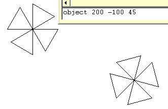
Now suppose that you want to draw this object at coordinates (x,y) and at an angle A to the vertical.
to object :xCo :yCo :angle This enables you to draw an object of your choosing, anywhere on the screen at any angle that you like. |

|
|
One solution to this problem, which also lays the foundation for a more advanced way of drawing objects is to always make object at one size but then magnify it by a scale factor.
to object :xCo :yCo :angle :scaleFactor "size is an example of a local variable. It is local to this instance of object and is not passed to any other procedures. This is useful as it prevents procedures messing each other up. |

|
Working with 2D Vector Graphics.
3D graphics is possible in two ways within Logo. This section will look at 2D graphics in a way that makes the better way of doing 3D graphics more accessible.
The aim is again to draw a an object which is made from a collection of points (vertices) joined by lines (edges). We will write several procedures to enable us to draw this object anywhere, at any angle, to any scale and distorted in various ways.
Object Drawing with Vectors | |||||||||||||||||
|
Think of the object as a collection of points which are joined by lines.
to object2 |

| ||||||||||||||||
|
A better way to do this is to turn the points into a list of coordinate pairs. These can be entered in the command line as follows:
make "a list 0 0 
|
We now need a program which can convert a coordinate list (of any length) into a drawing.
to draw :object This program takes the list which it calls object as its argument. It then moves the mouse to the first pair of coordinates in the list. To draw the object call draw at the command line with: draw :obj2 | ||||||||||||||||
Translation | |||||||||||||||||
|
Now we want to draw the object at any point (x,y) on the screen. To do this we need a procedure that will translate our object by the amount (x,y).
to trans :object :xCo :yCo First two local arrays are made to hold the pairs of coordinate points. |
To test this procedure we need to write a modifier to draw. This is because draw currently assumes that it is already in the correct place to begin drawing. The modified procedure is shown below.
to drawpos :object This simply moves the turtle position to the first coordinate pair in the list and then tells the program to get on and draw. Test the code with a command line call something like this: cs repeat 5 [drawpos trans :obj2 repcount*10 repcount*20] 
| ||||||||||||||||
Enlargement | |||||||||||||||||
|
The code for enlarging an object is very similar to that for translating it. The difference is that the coordinate pairs are multiplied by a scale factor rather than having a translation vector added.
to scale :object :xSc :ySc |
Test with this command line statement: cs repeat 5 [drawpos scale :obj2 repcount*4 repcount*1.5] 
An enlargement written in matrix notation. | ||||||||||||||||
Rotation | |||||||||||||||||
|
Rotation is harder to accomplish but the struggle is worth it because it paves the way for working in 3D. 
|
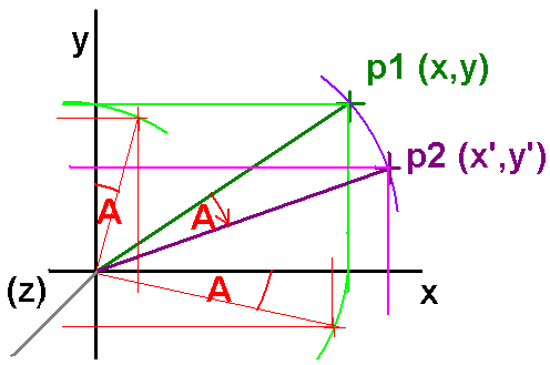
Think about what happens to the x and y components of the vector joining p1 to the origin. x'= xcosA + ysinA Whilst the y' coordinate is given by: y'= -xsinA + ycosA For reasons that will become obvious when we hit 3D this is more easily represented as a matrix multiplication of the position vector (x, y)
This is the standard matrix notation for a clockwise rotation A about the z axis which sticks out towards the viewer looking down on the xy plane. | ||||||||||||||||
|
So to turn this idea into a usable Logo procedure all we need is a procedure that will apply a general rotation A to our (x,y) coordinate pairs.
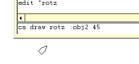
to rotz :object :A Test this code with our object :obj2 and this command line instruction: cs draw rotz :obj2 45 
| |||||||||||||||||
|
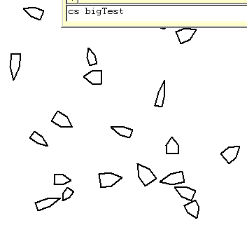
It is always worth giving your code a good testing. This is a procedure which invokes all three of our operations in sequence. It draws a randomly scaled and rotated version of obj2 at a random point on the screen. The process is repeated 20 times.
to bigTest |

| ||||||||||||||||
Last updated 23rd February 2010